I reverse engineered the hardware and firmware of my Egret GT E-Scooter. I describe how I got in, analysed communication between components, and reverse engineered firmware. I speak about writing custom firmware for the display unit.
Introduction
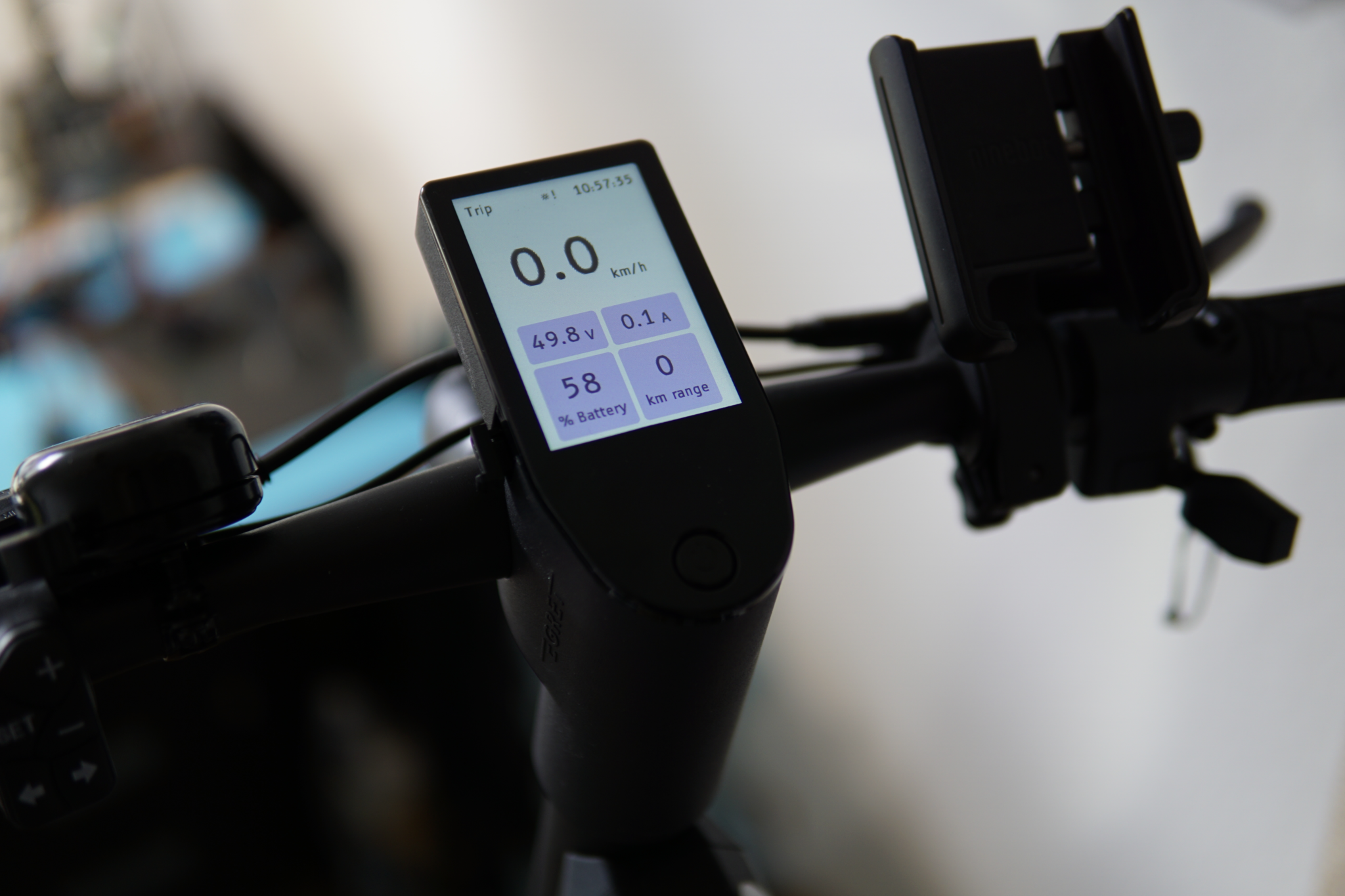
Last year, I bought myself an Egret GT. It’s an e-scooter that touts a range of 100km and has very large tyres which makes driving it quite comfortable. To make sure you know that it’s a high-end e-scooter, it comes with a 320x480 LCD display used as a HUD, on which the speed, driving mode, battery level and range are displayed.
Now because I have to break tinker with everything I own, I eventually decided to start figuring out how this thing worked. I can’t remember exactly why, but it was possibly due to the fact that holding the ‘down’ button on the keypad while powering the scooter would cause it to enter a firmware update mode. If you clicked a button to exit this menu, you would enter the normal ‘driving’ mode, and would be able to use the scooter without entering the PIN. While I always secure the scooter with a reasonably good lock, this still irked me a bit.
The first thing I started on was the mobile app, which allows you to unlock the scooter remotely, change a few settings, and view the battery level. I won’t bore you with the process, but what I found from skimming through the bluetooth handlers of the app was the following:
- The scooter can perform firmware updates over bluetooth, and seemingly there exists a few different places a firmware update can go (display, controller, button panel).
- Some metrics which are not shown in the app or on the scooter are transmitted over bluetooth, such as the time spent in each driving mode, device temperature, motor current, battery voltage, battery charging history. Details such as the total driving time, odometer, and charge history are transmitted to the manufacturer and stored attached to the scooter’s ID, this behaviour is not clearly mentioned in the app :)))))))
- The scooter doesn’t know its Vehicle Identification Number until the app connects and sets it. If you set this using a bluetooth debug app yourself, the Egret app can be spoofed to think the scooter is a different model. I tried to spoof the VIN of the 45km/h model of the scooter to see if the speed limit was implemented with such a simple check, but this didn’t work.
Eventually I became bored at playing with the bluetooth interface and turned to the USB-C port on the display. The manufacturer states that this is just for charging phones, and after some testing with different devices I did conclude that if the data pins were connected, the display unit wouldn’t act as either a USB host or device. But I knew better, and ordered a USB-C breakout board. When this arrived, I plugged it in and probed each pin with an oscilloscope. To my surprise, two of the USB-C pins were being used as a CAN bus (which smells horribly noncompliant).
CAN Bus sniffing
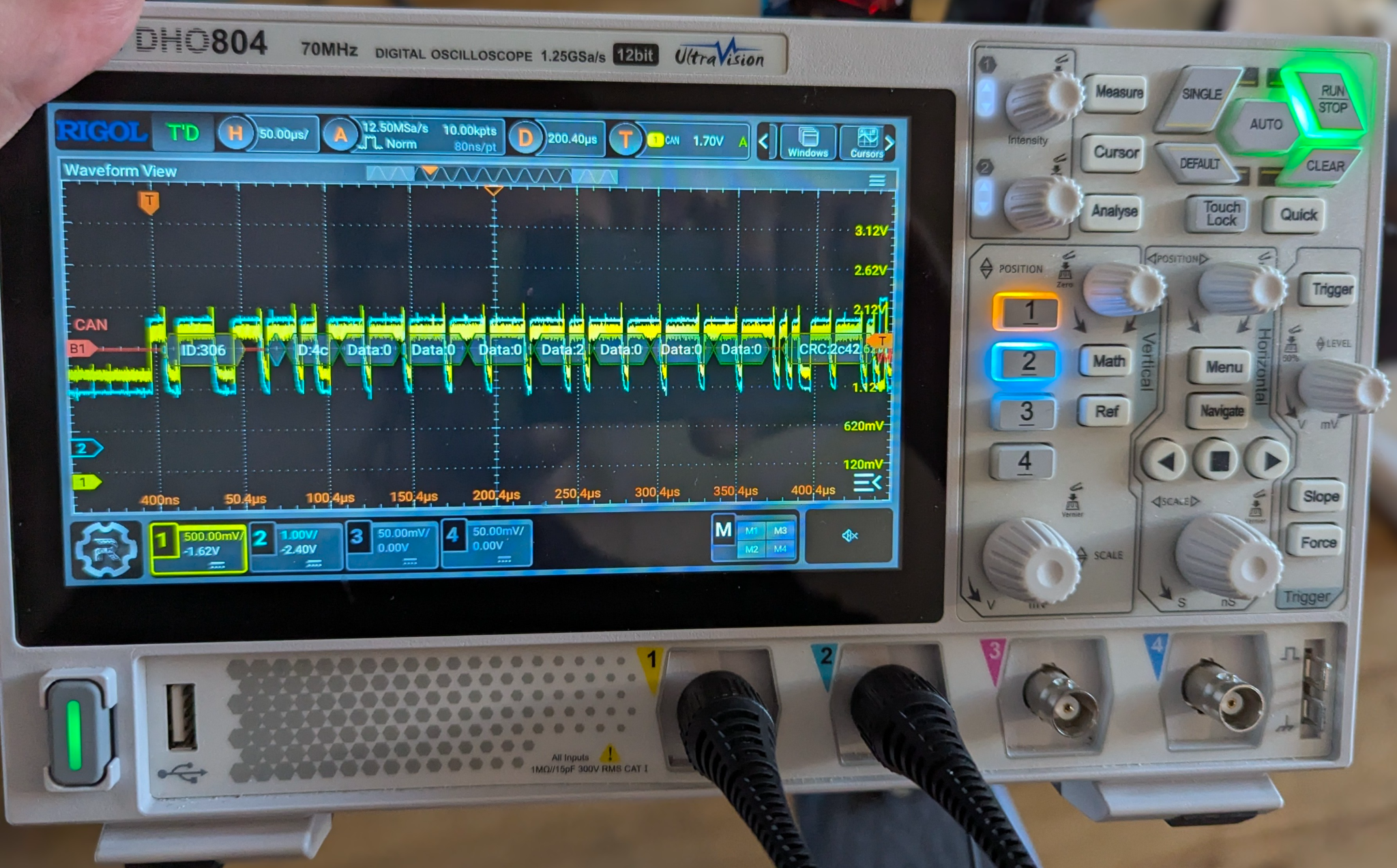
Figure 1: An oscilloscope attached to the CAN bus of the scooter, decoding messages.
To sniff this can traffic, I threw together an abomination (pictured in Figure 2) using an ESP32-C6, a SN65HVD230, and a MCP2515^0.
[^0]: The reason for two CAN transceivers is that the SN65HVD230 could be used by the ESP-CAN peripheral to listen to messages, but for some reason wasn’t able to transmit properly (would cause a bus error). I later added the MCP2515, which is able to transmit. I kept both because the SN65HVD230 exposed an async interface in the rust library I was using for the firmware, which makes receiving messages as part of a state machine easy.
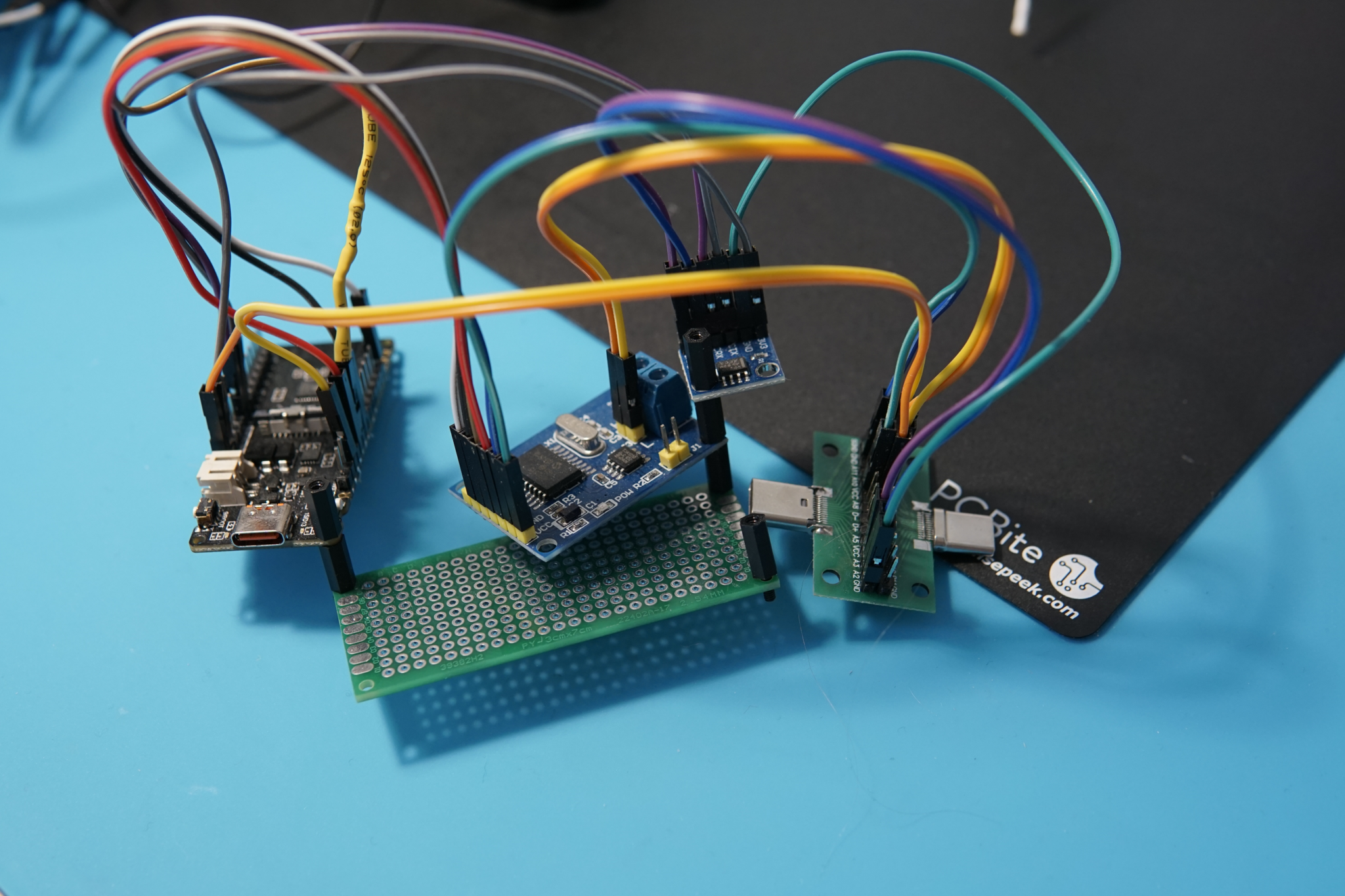
Figure 2: The device
I put together a quick program which initialised the CAN peripherals and logged every can message. Then I plugged my CAN logger into the scooter and recorded the messages during startup.
The CAN bus proved to be quite noisy, so to figure out what was going on I built a small tool using egui to show a plot of can messages against time. By plotting each can message as a dot with the y-axis as the can message ID, it becomes very easy to identify which messages are commands, responses, and periodic data.
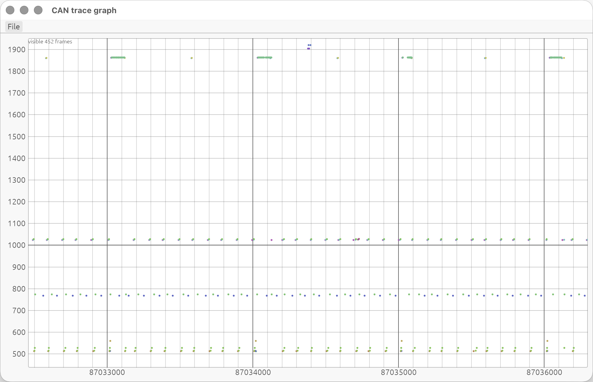
Unfortunately at this point I still didn’t have a good idea which purpose each message had. But by sniffing the bus while running the scooter, I was able to quickly figure out which messages were used in communicating the throttle, driving mode, and motor speed:
0x300: Sent by the display to the controller. Contains the current driving mode (walk, eco, drive, sport), whether the headlight is on, and in walk mode contains a counter in the last nibble. Sending a message where the fourth byte is a5 instead of the usual 5a causes the controller to reset.
An example is which decodes to:
Driving modeWalk (0x00_90)HeadlightOperating (0x64)Walk counter0
0x306: Sent by the display to the controller. Contains the throttle position, the blinker lights, and the speed limit of the scooter. The speed limit has no effect on the standard GT controller, but on the GTS it sets the speed limit to 25, 35, or 45km/h. For some reason the throttle level is transmitted as a 9 bit unsigned integer with the MSB being the first bit of the second byte.
An example is which decodes to:
Throttle511Left blinkertrueRight blinkerfalseSpeed limit25km/h (0)
0x201: Contains motor speed, and some status flags.
An example is which decodes to:
Motor speed1031Walk modefalseHeadlight onfalseBrake light ontrue
In the end, I documented all of the CAN messages: here.
At this point I was now able to do some amusing stuff, like controlling the scooter’s motor remotely, but this isn’t very practical or interesting. This project kind of stalled at this point as I had no access to the firmware and therefore there was little more I could do. A few months later I noticed that it was possible to buy replacement motor controller and display units online. I couldn’t resist the opportunity, so I ordered replacements of both.
Teardowns and firmware extraction
The first component I tore down was the controller. This was particularly difficult as the rear plate was secured very tightly with crosshead screws, of which the heads of two stripped immediately, requiring me to dremel a slot. The device was also filled with some type of potting compound, but very thankfully the compound was actually quite soft and could easily be scraped away.
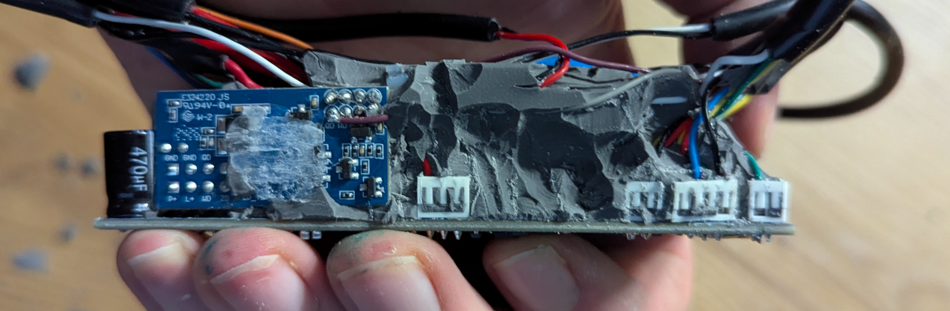
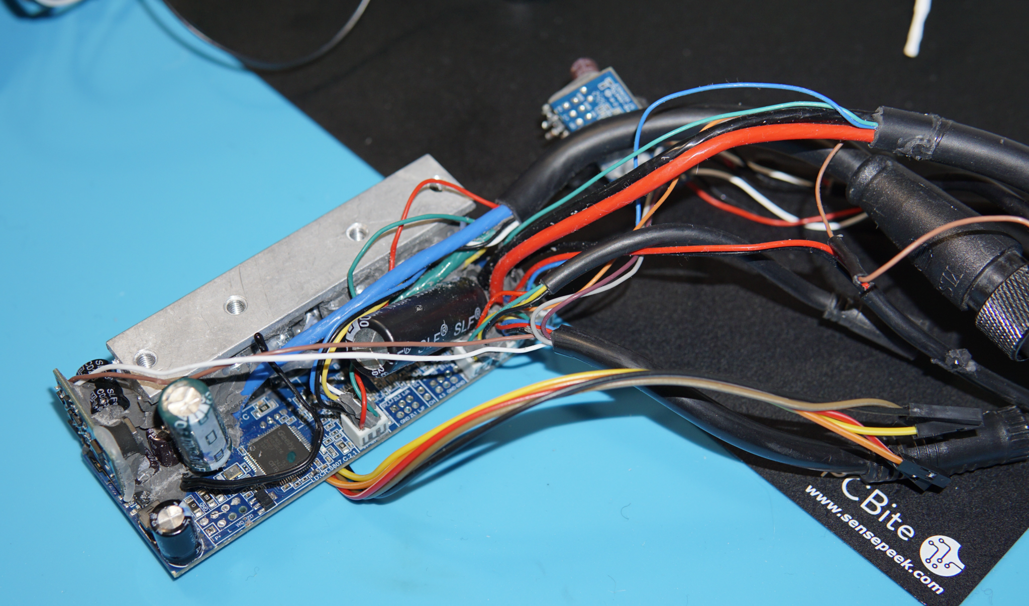
After removing the potting compound, I was presented with quite the gift: None of the active components had had their markings etched away, and there was a row of four pads on the back side of the board. The MCU was marked with APM32E103xCxE (a STM32F103 clone), therefore these pins are very likely the SWD port. By using OpenOCD^1 I was able to dump the flash and the RAM^2 contents shortly after boot.
[^1]: To dump images, I used a STLINK connected to these 4 pins (VCC, GND, CLK, DIO) and ran: openocd -f interface/stlink.cfg -f target/stm32f1x.cfg -c "init; dump_image flash.bin 0x00000000 0x80000; shutdown". For ram the command is the same, just with 0x20000000 instead of 0x0 as the base address.
[^2]: Capturing the RAM contents proved to be very useful as the firmware appears to store a lot of pointers in RAM which don’t change over the lifetime. Having these present gave Ghidra an easy time following references.
With the firmware dumped I could start analysing it with Ghidra^3. I very quickly found the main CAN message handler, which allowed me to further document the purpose of each CAN message.
[^3]: A quick rundown of how I did this:
- Import the flash image, set the language to
ARM Cortex little (default). Click options and set the base address to 0x8000000.
- Open the code browser, skip analysis for now.
- Use
File -> Add to program to add the RAM image, click options and set the base address to 0x20000000.
- Use the SVD loader plugin to load in the SVD file for the MCU. This is critical as it allows you to see clearly where peripherals (e.g. GPIO or the CAN bus) are being used.
- You should now run the analysis. Don’t enable aggressive instruction finder unless, I found it falsely identifies too many functions in data areas.
- Seek to
0x8000004, at this location is a pointer to the reset function (AKA main). Jump to the address and dissassemble/create a function if there isn’t one already.
- Start exploring from reset. There’s usually a lot of boilerplate HAL code here such as the clock setup and the code that loads static variables into RAM. There will likely also be a lot of noreturn functions here that ghidra won’t identify, which will cause decompiled code to appear in multiple locations. My only advice here is to click through until you see code that looks like application code - typically application code starts by initialising peripherals, so if you see GPIO/UART/CAN mentioned, you are probably in the right place.
- Be aware that the code starting at 0x8000000 might be the bootloader. If ghidra says the function modifies the stack pointer, this might be the ‘bootload’ function which is jumping to the main firmware by setting the stack pointer and jumping to the reset handler. If you look at the location where this function is taking the stack pointer and reset function from, you’ll likely find the interrupt vector of the main application.
Figure 3: Decompilation showing the handlers for messages 0x300 and 0x306
I also discovered that a total of three applications live on the controller MCU: A bootloader located at 0x8000000, an ‘updater’ at 0x8003000, and the main application at 0x8006200. The bootloader sets up the CAN bus and listens for a short time to see if any ‘update’ packets arrive, to see if a firmware update over the CAN bus is in progress. For some reason both the bootloader and ‘updater’ firmware contain a mechanism to update the application firmware over CAN bus, both use a different update scheme.
Figure 4: Ghidra open on the ‘bootload’ function of the controller. This can be identified by it writing the address of the reset function (image[1]) to the start of RAM (0x20000000), setting the stack pointer (image[0]), and then jumping to the reset function. The reset function will handle setting up the NVIC.
Figure 5: The application image. The first two words are the initial stack pointer address and the reset function, followed by the addresses of the interrupt handlers. Note how it’s quite repetitive, this makes it easy to identify.
Another funny note is that at 0x8006000 the length of the application firmware is stored, but not as a four or eight byte unsigned integer as you’d inspect, but instead as an ascii string of the base-10 representation of the number. Even wilder is that the entire region after the length up to 0x80061ff is padded with ascii space characters, and terminated with \r\n.
Figure 6: The contents of memory just before the main application starts.
After exploring a small amount further, I decided to turn my attention to the display unit. The majority of the code in the controller appears to be the FOC motor control code, and I didn’t feel particularly comfortable modifying the safety critical part of the device, especially after discovering that the controller contains some fairly reasonable safety precautions, such as shutting down if the display stops sending valid throttle positions after a short period.
Display unit
Cracking open the display unit required much more effort than the controller. It’s constructed from a reasonably tough and thick (2mm) injection molded body, so I used a dremel to cut into the back side. I had assumed the front screen cover was heat welded on, and so I also started using a dremel around the edge, but once I had cut a slot and had some leverage, I was able to simply pry the cover off as it was only glued.
Figure 7: Topside of the display unit, I’m using a Glasgow as the debugger
The board for the display was quite interesting as it had several unused through hole pin header rows and multiple microcontrollers. I identified the chips to be the following:
- Main MCU: AT32F415
- Bluetooth MCU: CH573
- NFC reader IC: FM17520
- CAN Transceiver
- SPI flash chip: W25Q128FV
One debug header was the SWD port for the main MCU, so I repeated the process of dumping the firmware there. Another provided access to the SPI flash, so I also dumped this, but it only contained only the bitmap images used by the GUI shown on the display.
The display firmware is structure similarly to the control unit, with a bootloader which is capable of receiving firmware updates over the CAN bus.
- The display unit firmware is structured as a bootloader and a main application at 0x8008000.
- The GUI is drawn using SEGGER EMWin.
- The bluetooth MCU communicates over GPIOA 2 and 3 using UART at 57500k, using a simple framing scheme. When a bluetooth attribute is read, the CH573 sends a request message with a number indicating a handler in the main MCU firmware. The main MCU sends back a response message with the same command number and the response body.
- The NFC module also communicates over UART at 115200k, with a slightly different protocol. I didn’t look into this much further.
- The button panel on the handlebars of the scooter communicates with the display unit also over UART, at 9600k. The only message it sends is a simple bitfield of the buttons that are pressed. Interestingly, it handles the blinking of the indicators itself; It blinks the lights and also has two bits in its message which indicates the blinker state. It appears to also be able to receive firmware updates.
- The CAN bus is connected over pins GPIOA 11 and 12.
- The display is a ST7796 controller, connected over a parallel interface; All 16 pins on GPIOB are used as a parallel data bus, which allows the firmware to update the state of all pins in just one instruction.
- The ADC reads from three channels: An ambient light sensor on ch12, the throttle voltage on ch13, and the battery voltage on ch15. The firmware only reads the battery voltage to trigger an error message when it is too low, for all other usages of the battery level the firmware reads a variable updated by a CAN message sent by the battery. (Yeah, the battery is on the bus.)
- The firmware of the display unit is, like the controller, updated over CAN. And again like the controller, the actual update code lives in the bootloader; The application firmware simply reboots itself if it sees an update initiation message, the bootloader then sees the next message and starts the update process. Yes, this also means that it’s possible to modify the firmware of any scooter without authentication :)))))
Initially the display firmware was a pain to reverse engineer, the version of Ghidra that I was using had a bug which caused it to not properly tag function pointers located in areas identified as data, due to the pointers having their lower bits set (indicating that the function uses THUMB instructions). Since the firmware is structured around tables of callbacks - for CAN, bluetooth, and GUI screens - I was unable to locate the callers of a lot of functions. By luck I at some point encountered the function which scans through the CAN handlers table and was able to ascertain the structure of the CAN handler table, and since every entry in the table specifies the ID to match on, and optionally an interval and a tx and/or rx callback, I was now able to quickly locate the corresponding code for each CAN message that I observed.
Figure 8: Ghidra with the function of the display unit which handles sending the 0x300 CAN message
Figure 9: A table of CAN handlers defined at 0x200001a0
Figure 10: The entry for CAN message 0x306, it has a transmit callback and a specified interval
Through extensive cross referencing of both the display and controller firmware, I was able to build up a mostly complete understanding of the CAN messages, the only messages I didn’t complete were some related to the apple find my feature, which I’m not particularly interested in because I don’t have an iphone and instead built my own tracker device using openhaystack, which has the extra benefit of not triggering any ‘tracker following’ messages as it rotates identity every 30 minutes :)
Next up was figuring out the GPIO and peripheral configurations, which I’d need to begin writing my own firmware. Thankfully this is actually pretty easy as the firmware is using the manufacturer provided peripheral library and also didn’t use any form of LTO when compiling, so the decompilation output for the compiled HAL provided functions very closely matches the source.
Figure 11: Decompilation result for the GPIO_Init function, which is pretty much identical to the source
Figure 12: Decompilation of the function initialising UART5, we can see which pins are statically configured as tx and rx by the contents of the GPIO_Pins field, and the configuration of the UART peripheral. The baud rate is passed as a parameter for some reason.
Using this technique of matching up decompiled library functions with source code, and using the name and type information obtained by doing so to discover peripheral configs, allowed me to fully map out all the GPIO pins and the configurations of all the peripherals..
Another thing that aided in my reverse engineering was that the firmware had left in a debug menu (it seems to be unreachable from the actual firmware, but the code is still there). The debug menu displays some button and headlight statuses, so I was instantly able to fill out a ‘button state’ enum.
Figure 13: Decompilation of the debug menu
At this point I had pretty much figured out enough information to begin writing my own firmware; The CAN messages required to operate the motor controller were fully mapped out, as were the GPIO pins and peripheral configurations, and I’d also reverse engineered the UART protocol of the bluetooth MCU. I’d even put together a block diagram of all the individual components of the scooter that communicate:
Running my own firmware on the cracked open display unit would be trivial, as I can just use a debug probe to flash it. But to get my firmware onto a usable display unit I’d need to reverse engineer the firmware update process.
Firmware updates
Thankfully (for me) the firmware update process ended up being extremely simple, with no cryptography involved and the main lifecycle of a firmware update living entirely within one function in the bootloader.
A firmware update starts in a CAN message handler for ID 0x384. If the message is then the firmware resets, and if the message is then the scooter erases the flash regions used to store the VIN and scooter configuration.
Figure 14: Ghidra with the function of the display unit which handles CAN messages with ID 0x384
Figure 15: The core of the firmware update loop, after a chunk’s CRC is validated, the bootloader directly writes into flash.
The device performing the firmware update then continues to send messages until the bootloader starts up, sees an update initiation message, and replies with . The updater device then sends 64 byte chunks spread over 9 CAN 0x384 frames, where each frame has the following structure:
- Frame 0
- Frame 1..9
- Frame 9
The CRC is CRC-16-CCITT over the data. The data of each chunk is padded with zeros to make 64 bytes before calculating the CRC. sequence is an unsigned byte, starting at 0 and incrementing for each chunk transmitted, after 0xFF it wraps to 0.
The first chunk is not the first 64 bytes of the firmware, but instead the update file name (for example: AT_R2_JHZY_GT1_GE_FM_HW02_4.0.2) as a null terminated string, followed by the firmware length as a base-10 encoded, null terminated string. The bootloader replies to the first chunk four times with , and all subsequent chunks with one .
After the first chunk is sent, the updater device then sends the firmware image a chunk at a time. The scooter replies with one message after the last CAN message of a frame is sent and the CRC is validated. After the firmware has been transmitted, the updater sends , which triggers a reboot of the display unit. The update mechanism directly writes over the application image in flash, so a failed update will brick the display. However, the bootloader always checks for the presence of packets when powering up, allowing a firmware update to begin even if the application code isn’t functional.
In summary, the update process follows this sequence diagram (you can tell I’m having fun with typst here :)):
Figure 16: Sequence diagram of update process
To actually do the firmware update, I extended the CAN dumping firmware that I wrote earlier into this, which simply flashes a firmware image embedded inside.
Great, I can now update the firmware on the device. To confirm this worked I tried it out with the firmware image I’d dumped from the cracked open device to begin with, and it worked first time.
Rewrite it in rust
Now I could begin writing some firmware in Rust. There was a small problem though, the display unit MCU is the AT32F415, which is a STM clone, but it seems to not be a clone of a specific STM chip, but instead a mish-mash of STM32 peripherals, most appear to match up with the STM32F1, but the RTC seems to be from a STM32F3. This is annoying because it means I can’t just jumpstart to writing firmware using Embassy, instead I need to first build my own HAL^4.
[^4]: Hardware access library.
Kossnikita had already started on this using a fork of stm32-rs, so I was thankfully able to take this and start adding support for the peripherals I needed. I must admit I mostly cheated here; for most of the peripherals I started by taking the implementation from Embassy, and then I, with both the datasheet of the stm32f1 and the at32f415 open, updated the peripheral code to match the register names used by the AT32. There’s very likely a better way here, such as adding the chip as an entry in stm32-metapac, which is a subproject of Embassy which processes SVD files to create PAC^5 crates, but I initially assumed the AT32 was more different than it is.
[^5]: Peripheral Access Crate.
I started by bringing up each peripheral, the clocks and timers first, as a timer allows me to add an embassy-time-driver implementation. Then the ADC, external GPIO interrupts, UART, CAN, and RTC peripherals. With the HAL drivers implemented I could then start writing code to drive the display, read the ADC inputs, and talk over the CAN and UART buses.
Bringing up the display was entirely straightforward, using the mipidsi crate for the display driver, all I had to do myself was add a ParallelInterface implementation in the HAL that allows writing a u16 to all the GPIO pins in one operation:
/// A bus of gpio pins
///
/// SHIFT: which range of pins are we operating on: 0 => 0..16, 8 => 8..16
/// MASK: bitmask used to select which pins are members of this bus. The mask is unshifted.
pub struct Bus<const P: char, const SHIFT: u8, const MASK: u16, MODE = DefaultMode> {
    _mode: PhantomData<MODE>,
}

impl<const P: char, const SHIFT: u8, const MASK: u16, MODE> Bus<P, SHIFT, MASK, MODE> {
    fn _set_state(&mut self, state: u16) {
        unsafe {
            (*Gpio::<P>::ptr()).odt().modify(|r, w| {
                // we only need to read the previous state if the mask doesn't
                // cover everything.
                let prev = if const { MASK & 0xFFFF != 0xFFFF } {
                    r.bits() & !(MASK as u32)
                } else {
                    0
                };

                let new = ((state << SHIFT) & MASK) as u32;
                w.bits(prev | new)
            });
        }
    }

    fn _get_state(&self) -> u16 {
        unsafe {
            let unshifted = (*Gpio::<P>::ptr()).odt().read().bits() & !(MASK as u32);
            (unshifted >> SHIFT) as u16
        }
    }
}

impl<const P: char, const SHIFT: u8, const MASK: u16> mipidsi::interface::OutputBus
    for Bus<P, SHIFT, MASK, Output>
{
    type Word = u16;

    const KIND: mipidsi::interface::InterfaceKind = InterfaceKind::Parallel16Bit;

    type Error = Infallible;

    #[inline(always)]
    fn set_value(&mut self, value: Self::Word) -> Result<(), Self::Error> {
        self.set_state(value);
        Ok(())
    }
}
We can then declare the pins used in the display as rust types:
pub type Bus = at32f4xx_hal::gpio::Bus<'B', 0, 0xFFFF, Output>;
pub type CsPin = Pin<'C', 13, Output>;
pub type DcPin = Pin<'C', 14, Output>;
pub type RdPin = Pin<'C', 0, Output>;
pub type WrPin = Pin<'C', 15, Output>;
pub type RstPin = Pin<'C', 1, Output>;
pub type Backlight = PwmChannel<at32f4xx_hal::pac::TMR2, 0>;

pub type InnerDisplay = mipidsi::Display<
    mipidsi::interface::ParallelInterface<Bus>,
    mipidsi::models::ST7796,
    RstPin,
>;

pub fn init(
    mut rd: RdPin,
    mut cs: CsPin,
    dc: DcPin,
    wr: WrPin,
    rst: RstPin,
    bus: Bus,
    delay: &mut SysDelay,
    backlight: Backlight,
) -> Display {
    cs.set_low();
    rd.set_high();

    let interface = mipidsi::interface::ParallelInterface::new(bus, dc, wr);
    let mut display = mipidsi::Builder::new(mipidsi::models::ST7796, interface)
        .reset_pin(rst)
        .invert_colors(mipidsi::options::ColorInversion::Inverted)
        .orientation(mipidsi::options::Orientation {
            rotation: mipidsi::options::Rotation::Deg0,
            mirrored: true,
        })
        .color_order(mipidsi::options::ColorOrder::Bgr)
        .init(delay)
        .unwrap();

    Display {
        _cs_pin: cs,
        _rd_pin: rd,
        inner: display,
        backlight,
    }
}
And now we have a Display which we can draw to. By opening up the compiled firmware in Ghidra we can also confirm that the data transmission loop turns into a simple loop which writes a sequence of bytes to a single MMIO register:
void __rustcall mipidsi::interface::parallel::send_command<>(
    ParallelInterface<> *self,
    u8 command,
    &[u8] args
) {
  byte *pbVar1;
  u8 *puVar2;

  _DAT_40010c0c = command & 0xff;
  _DAT_422202b8 = 1;
  _DAT_42220238 = 1;

  pbVar1 = args.data_ptr;
  for (puVar2 = args.len; puVar2 != 0x0; puVar2 = puVar2 + -1) {
    _DAT_40010c0c = *pbVar1;
    pbVar1 = pbVar1 + 1;
    _DAT_422202bc = 1;
    _DAT_4222023c = 1;
  }

  return;
}
With the display working, I next worked on implementing encoding and decoding of the CAN and bluetooth protocols. For this I used deku as it allows you to declare byte and bit level parsers for structs using a quite concise macro^6:
[^6]: The full protocol implementation can be found here
/// 513
#[derive(deku::DekuRead, deku::DekuSize, defmt::Format, Clone, PartialEq, Eq)]
#[cfg_attr(test, derive(deku::DekuWrite, Debug))]
#[deku(bit_order = "lsb", endian = "little")]
pub struct ControllerSpeed {
    /// In km/h * 100
    #[deku(pad_bytes_after = "2")]
    pub motor_speed: u16,

    #[deku(bits = 1)]
    pub walk_mode: bool,

    #[deku(bits = 1)]
    pub headlight_on: bool,

    #[deku(bits = 1, pad_bits_after = "5")]
    pub brake_light_on: bool,
}

#[test]
fn test_display_throttle() {
    let mut buf = [0u8; 8];

    deser_roundtrip(&mut buf, &DisplayThrottle::new(511, false, false, 0));
    assert_eq!(buf, [0xff, 0b1, 0x00, 0x00, 0x02, 0x00, 0x00, 0x00]);

    deser_roundtrip(&mut buf, &DisplayThrottle::new(511, true, false, 0));
    assert_eq!(buf, [0xff, 0b011, 0x00, 0x00, 0x02, 0x00, 0x00, 0x00]);

    deser_roundtrip(&mut buf, &DisplayThrottle::new(511, true, true, 2));
    assert_eq!(buf, [0xff, 0b111, 0x00, 0x02, 0x02, 0x00, 0x00, 0x00]);

    deser_roundtrip(&mut buf, &DisplayThrottle::new(1, false, true, 2));
    assert_eq!(buf, [0x01, 0b100, 0x00, 0x02, 0x02, 0x00, 0x00, 0x00]);

    deser_roundtrip(&mut buf, &DisplayThrottle::new(256, false, true, 2));
    assert_eq!(buf, [0x00, 0b101, 0x00, 0x02, 0x02, 0x00, 0x00, 0x00]);
}
The neat thing about doing this in rust is that I could then take these definitions and use them in a completely different program to decode the CAN logs into something human readable.
Actor-modelling
Now that the protocols are implemented, it becomes quite easy to write state machines using Embassy to handle incoming messages (both external messages from the CAN bus or bluetooth MCU, or internally defined messages for communicating button presses, events triggered by the UI, and ADC readings) and update relevant state. Overall, using the actor model for firmware is really quite a breeze, when all tasks communicate over well defined interfaces instead of reading and writing to shared global memory, reasoning about the system becomes simplified, and in my case, writing an emulator tool to test the GUI proved easy.
In the end, I ended up with this set of actors and relationships:
Figure 17: Diagram of tasks (Grey) and resources (Coloured). Arrows indicate direction of data flow.
The ADC Task
This task reads the ADC periodically, and publishes readings onto a channel that other tasks can subscribe to.
pub static ADC_READINGS: embassy_sync::pubsub::PubSubChannel<
    embassy_sync::blocking_mutex::raw::CriticalSectionRawMutex,
    AdcReading,
    4,
    4,
    1
> = embassy_sync::pubsub::PubSubChannel::new();

pub static THROTTLE_READINGS: embassy_sync::watch::Watch<
    embassy_sync::blocking_mutex::raw::CriticalSectionRawMutex,
    Throttle,
    4
> = embassy_sync::watch::Watch::new();

pub static AMBIENT_READINGS: embassy_sync::watch::Watch<
    embassy_sync::blocking_mutex::raw::CriticalSectionRawMutex,
    AmbientLight,
    4
> = embassy_sync::watch::Watch::new();

async fn adc_task_(
    mut adc: Adc<ADC1>,
    // ambient light
    ch12: Pin<'C', 2, Analog>,
    // throttle
    ch13: Pin<'C', 3, Analog>,
) {
    let mut do_sample_ticker =
        embassy_time::Ticker::every(Duration::from_millis(50));

    let state_reading_ch = ADC_READINGS.publisher().unwrap();
    let throttle_reading_ch = THROTTLE_READINGS.sender();
    let ambient_reading_ch = AMBIENT_READINGS.sender();

    // the ambient light level is averaged so that it doesn't flicker
    let mut ambient_light_averager = MovingAverage::<u16, u32, 16>::new();

    loop {
        // sample the throttle and ambient light every 50ms
        do_sample_ticker.next().await;

        defmt::trace!("ADC measuring ambient");
        let val = adc.convert(&ch12, SampleTime::Cycles_480).await;
        let avg = ambient_light_averager.average(val);
        let ambient_light = AmbientLight::from_raw(avg);

        state_reading_ch
            .publish(AdcReading::AmbientLight(ambient_light))
            .await;

        ambient_reading_ch.send(ambient_light);

        defmt::trace!("ADC measuring throttle");
        let val = adc.convert(&ch13, SampleTime::Cycles_480).await;
        let thr = Throttle::from_raw(val);

        state_reading_ch
            .publish(AdcReading::Throttle(thr))
            .await;

        throttle_reading_ch.send(thr);
    }
}
To handle converting raw ADC readings to usable numbers, I use the following newtype pattern:
#[derive(Eq, PartialEq, Default, defmt::Format, Clone, Copy, Debug)]
pub struct Throttle(pub u16);

impl Throttle {
    pub const INITIAL: Self = Self(0);

    // value we report to the controller when throttle is fully depressed
    const OUT_MAX: u32 = 360;

    fn from_raw(raw: u16) -> Self {
        // value the adc reads when throttle is fully depressed
        const MAX_RAW: u32 = 2820;

        // value the adc reads when the throttle is unpressed
        const MIN_RAW: u32 = 730;

        Self(
            (raw as u32)
                .clamp(MIN_RAW, MAX_RAW)
                .saturating_sub(MIN_RAW)
                .saturating_mul(Self::OUT_MAX)
                .saturating_div(MAX_RAW - MIN_RAW)
                .saturating_truncate(),
        )
    }

    pub(crate) fn for_bluetooth(&self) -> u8 {
        const MAX_BT: u32 = 146;

        (self.0 as u32)
            .saturating_mul(MAX_BT)
            .saturating_div(Self::OUT_MAX)
            .saturating_truncate()
    }

    pub fn adjust_for_speed_limit(
        &self,
        // current speed limit setpoint (e.g. 271)
        speed_limit: u16,
        // speed limit set on the controller
        // (250/350/450). for a speed_limit of 271
        // this should be 350.
        controller_speed_limit: u16,
    ) -> u16 {
        // This is just a linear scale for now. I need to find how the speed
        // actually responds over throttle values.
        (self.0 as u32)
            .saturating_mul(speed_limit as u32)
            .saturating_div(controller_speed_limit as u32)
            .saturating_truncate()
    }
}
The ‘System state’ task
The system state (I’m bad at naming) task is used to maintain the read-only and calculated state of the system, that is: The battery level, current speed, temperature, and the odometer and predicted range.
#[derive(PartialEq, Eq, defmt::Format, Clone)]
pub struct SystemState {
    /// motor speed, in deca meters per hour (speed / 100 = km/h)
    pub motor_speed: u16,
    pub headlight_on: bool,
    pub brake_light_on: bool,

    pub controller_temp: u8,
    pub system_voltage: SystemVoltage,
    pub controller_speed_limit_mode: bool,

    pub battery_current: i16,
    pub battery_debug: BatteryDebug,
    pub battery_info: BatteryInfo,

    pub throttle: Throttle,
    pub ambient_light: AmbientLight,

    pub buttons: Buttons,
    /// in km
    pub odometer: u16,

    /// in km
    pub predicted_range: u16,
}

#[embassy_executor::task]
async fn system_state_updater() {
    let can_messages = CAN_MESSAGES.receiver();
    let bt_commands = BT_COMMANDS.receiver();
    let mut adc_readings = crate::adc::ADC_READINGS.subscriber().unwrap();
    let state_updated = STATE_UPDATES.sender();
    let mut buttons_reader = BUTTON_STATE_WATCH.receiver().unwrap();

    let mut update_private_state_ticker =
        Ticker::every(Duration::from_secs(PRIVATE_STATE_UPDATE_PERIOD_SECS));

    let mut private_state = PrivateState::default();

    loop {
        let updated = match select::select5(
            can_messages.receive(),
            bt_commands.receive(),
            adc_readings.next_message_pure(),
            buttons_reader.changed(),
            update_private_state_ticker.next(),
        )
        .await
        {
            select::Either5::First(can_msg) => {
                update_state(|s| s.update_from_can_message(&can_msg));
                private_state.update_from_can_message(&can_msg);
                true
            }
            select::Either5::Second(_) => false,
            select::Either5::Third(reading) => {
                update_state(|s| s.update_from_adc_reading(reading))
            }
            select::Either5::Fourth(buttons) => {
                update_state(|s| s.buttons = buttons);
                true
            }
            select::Either5::Fifth(_) => {
                private_state.periodic_update();
                update_state(|s| private_state.update_public(s));
                true
            }
        };

        if updated {
            state_updated.send(());
        }
    }
}

impl SystemState {
    pub fn update_from_can_message(&mut self, msg: &CanMessage) {
        match msg {
            CanMessage::ControllerStatus(ControllerStatus { battery_level, .. }) => {
                self.battery_info.level_from_controller = *battery_level;
            }
            CanMessage::ControllerSpeed(ControllerSpeed {
                motor_speed,
                headlight_on,
                brake_light_on,
                ..
            }) => {
                self.motor_speed = *motor_speed;
                self.headlight_on = *headlight_on;
                self.brake_light_on = *brake_light_on;
            }
            CanMessage::ControllerTempMotor(ControllerTempMotor { temp, voltage }) => {
                self.controller_temp = *temp;
                self.system_voltage.from_controller = *voltage;
            }
            CanMessage::ControllerSpeedMode(ControllerSpeedMode { .. }) => {}
            CanMessage::ControllerSpeedLimit(ControllerSpeedLimit { speed_limit }) => {
                self.controller_speed_limit_mode = *speed_limit;
            }
            CanMessage::BatteryCommandState(BatteryCommandState {
                command,
                state,
                estimated_range,
            }) => {
                self.battery_debug = BatteryDebug {
                    command: *command,
                    state: *state,
                    estimated_range: estimated_range.truncate(),
                }
            }
            CanMessage::BatteryVoltageCurrent(BatteryVoltageCurrent {
                voltage_mv,
                current_ma,
            }) => {
                self.system_voltage.from_battery = voltage_mv.truncate();
                self.battery_current = current_ma.truncate();
            }
            CanMessage::BatteryChargeLevel(BatteryChargeLevel {
                relative_soc,
                absolute_soc_mah,
            }) => {
                self.battery_info.relative_soc = relative_soc.truncate();
                self.battery_info.absolute_soc = absolute_soc_mah.truncate();
            }
            CanMessage::BatteryStateOfHealth(BatteryStateOfHealth {
                relative_soh,
                absolute_soh_mah,
            }) => {
                self.battery_info.relative_soh = *relative_soh;
                self.battery_info.absolute_soh = absolute_soh_mah.truncate();
            }
            CanMessage::BatteryCapacityTemp(BatteryCapacityTemp {
                capacity_mah,
                battery_charged,
                battery_charging,
                battery_temp,
            }) => {
                self.battery_info.capacity = *capacity_mah;
                self.battery_info.charged = *battery_charged;
                self.battery_info.charging = *battery_charging;
                self.battery_info.temperature = *battery_temp;
            }
            _ => {}
        }
    }
}